ADC Snap
- Remove this product from my favorite's list.
- Add this product to my list of favorites.
Quick Overview
Tetracam's Ultra-Fast 90 Gram
Multi-spectral Imaging System with Electronic Global Snap Shutter

Tetracam's Ultra-Fast 90 Gram
Multi-spectral Imaging System with Electronic Global Snap Shutter
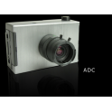
The ADC Snap is housed in the same package as the ADC Micro. It has the same weight, power consumption and interface connections as the ADC Micro. The cameras major difference is that it uses a 1.3 MPel electronic global snap sensor (1280 x 1024pixels). Unlike previous ADC systems, the ADC Snap exposes the entire image at the same instant in time. For this reason, this system does not experience rolling shutter problems. The ADC Snaps exposure time is so fast that engineers in our labs use this camera to capture stop-action photos of fan blades on their desks. These stop action cameras operate at speeds comparable to industrial machine vision cameras.
The CMOS sensor in the ADC snap does not use a rolling shutter as do the CMOS sensors in other cameras of the ADC line. Instead, it uses an electronic global snap shutter. It also has much larger pixels and better NIR response. This means that the ADC snap does not have motion distortion in captured images, and that its exposure times are short enough to eliminate motion blurring in the image as well. Practically, this means that the ADC snap pictures can be taken at lower altitudes and/or higher speeds than the other cameras in the ADC family. The ADC Snap camera is ideal for use with fast or low-flying UAVs, especially fixed wing aircraft susceptible to pitch, roll or yawing problems. It also means that the images will be easier to time with various mosaic building software packages. The implementation of the global electronic shutter in the ADC snap sensor produces raw images(images coming directly off the sensor) that have not had dark current noise removed. This is done later, when the images are transferred to a host computer.
The order of the pixels in raw images is also scrambled, from a conventional sensor point of view, and the pixels are reordered when transferred to the host as well. For this reason, the images taken by the ADC Snap camera have different file extensions than those of the rest of the ADC family. The unusual pixel order results in the appearance of vertical lines in the raw unprocessed image. This is because the red, green, and NIR pixels are grouped together in columns of four. Since the response of the three color filters is slightly different, green pixels appear brighter, while red and blue pixels are darker.
The image that is captured on the ADC Snap sensor is made up of 1280 x 1024 pixels (1.3 MPel). Images are stored along with metadata such as GPS coordinates and/or attitude information (pitch, roll and yaw) that is sent to the system through the ADC Snap's serial interface (see I/O connections described below). Metadata helps users establish the ground location of each image.
The ADC Snap's SD memory is easily accessible by the user. After missions are completed, users remove the Micro SD memory from the camera and transfer its contents to a host computer equipped with PixelWrench2, the software included with all Tetracam systems.
PixelWrench2 provides color processing of Tetracam RAW and DCM files, complex batch processing tools, a comprehensive suite of image editing tools and the ability to extract various vegetation indices such as NDVI from the captured images.
In addition to indicating plant stress, vegetation indices such as NDVI enable users to deduce information such as biomass, chlorophyll concentration in leaves, plant productivity and fractional vegetation cover as well as predict crop yield. Refer to System Application Notes for descriptions of example applications.
The ADC Snap is housed in the same package as the ADC Micro. It has the same weight, power consumption and interface connections as the ADC Micro. The cameras major difference is that it uses a 1.3 MPel electronic global snap sensor (1280 x 1024pixels). Unlike previous ADC systems, the ADC Snap exposes the entire image at the same instant in time. For this reason, this system does not experience rolling shutter problems. The ADC Snaps exposure time is so fast that engineers in our labs use this camera to capture stop-action photos of fan blades on their desks. These stop action cameras operate at speeds comparable to industrial machine vision cameras.
The CMOS sensor in the ADC snap does not use a rolling shutter as do the CMOS sensors in other cameras of the ADC line. Instead, it uses an electronic global snap shutter. It also has much larger pixels and better NIR response. This means that the ADC snap does not have motion distortion in captured images, and that its exposure times are short enough to eliminate motion blurring in the image as well. Practically, this means that the ADC snap pictures can be taken at lower altitudes and/or higher speeds than the other cameras in the ADC family. The ADC Snap camera is ideal for use with fast or low-flying UAVs, especially fixed wing aircraft susceptible to pitch, roll or yawing problems. It also means that the images will be easier to time with various mosaic building software packages. The implementation of the global electronic shutter in the ADC snap sensor produces raw images(images coming directly off the sensor) that have not had dark current noise removed. This is done later, when the images are transferred to a host computer.
Featuring 2GB standard storage (extensible to 16 GB), fast parallel processing, ultra-low power consumption, and simple menu-organized configuration and control, the ADC Snap contains a 1.3 mega-pixel sensor optimized for capture of visible light wavelengths longer than 520 nm and near-infrared wavelengths up to 920 nm.
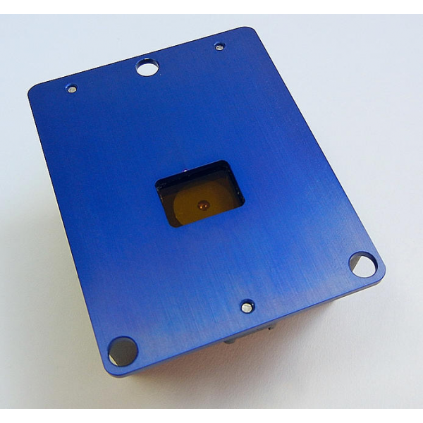
The ADC Snap and its accompanying software, PixelWrench2, are ideally suited for capturing and analyzing multi-spectral images of crops, forests and other eco-systems. The ADC MIcro possesses a high-quality 8.43 mm lens. The lens focuses the light that enters the camera on to the system's multi-spectral Snap Shutter image sensor.
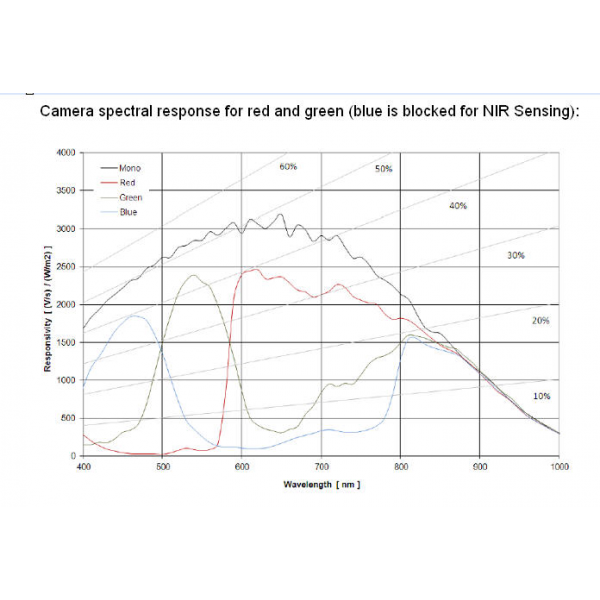
Three filters atop the sensor limit the radiation that enters it to bands of green, red and near-infrared radiation equivalent to Landsat Thematic Mapper bands TM2, TM3 and TM4. These bands are the basis for the standard "false color" composite images that have become associated with multi-spectral imagery. They provide excellent early warning signs of plant stress and their use as indicators of other specific plant and soil conditions has been documented by scientists for decades.
The graph above shows the response of the sensor to different bands of light through the red, green and blue filters. A blue absorbing glass filter is used to eliminate the blue sensitivity, and the blue pixels in the sensor are used to measure NIR (Yellow Curve). The image is then processed in Pixelwrench2 to subtract the measured NIR from the blue and red bands to produce the final Red/Blue/NIR image
ADC Snap (with 8.43 mm Lens)
Ground Resolution & FOV Examples
The ADC Snap enables users to gather information about vegetation at wavelengths traditionally monitored by satellites. Only, flying in manned or unmanned aircraft, data gathered by the ADC Snap is captured at times completely determined by the user, independent of satellite latency, un-obscured by cloud cover and in images that show considerably higher detail than images captured from space (i.e., with resolutions measured in millimeters per pixel rather than meters per pixel).
The ADC Snap's field of view (FOV) is laid out in a 4:3 format. The horizontal angle of view for the system is 37.67 degrees. The vertical angle of view is 28.75 degrees. When carried in a manned or unmanned aircraft, the field of view increases as the above ground level (AGL) altitude increases.
As the AGL increases, the camera's ability to resolve individual details on the ground decreases. With its standard 8.43 mm lens, when flown at altitude of 400 feet (122 meters) above ground level, this camera creates an image large enough to capture an area measuring 95 meters wide by 71 meters high at a resolution of less than two inches (46.3 mm) per pixel in a single shot.
Below is a table that shows the ground resolution and field of view for images gathered at various altitudes above ground. PixelWrench2 contains an FOV Optical Calculator that enables determination of the system's field of view and ground resolution for any user-specified altitude. For operation in the field, this utility is also available as a free app that runs on Android cell phones. For information on this app, click here.
System Controls, Indicators and Connections
ADC Snap Interconnection Pins
The ADC Snap contains labeled interconnection pins at the top of the front panel. These connect to the Un-terminated System Integration Cable and to the ADC Snap Test and Control Box Assembly and Cable, both of which are supplied with the system. The Un-terminated System Integration Cable may be used to connect the camera to external devices in a manned or unmanned aircraft such as an autopilot, GPS or video transmitter.
Pin 15 GND System Ground
Pin 14 +3VOUT +3.3 Volts accessory power
Pin 13 VIDGND Video ground reference
Pin 12 VIDEO NTSC or PAL Video signal out. The video format is controlled by the SETTINGS.TXT file. Video coax cables should be used for connecting video devices.
Pin 11 SPARE Unused input.
Pin 10 GRNLED READY
Pin 9 REDLED BUSY
Pin 8 RS232RX (GPS IN)
Pin 7 RS232TX Serial Output
Pin 6 SYNC GPS Sync event input pin
Pin 5 SHUTTER Ground to take a picture
Pin 4 DOWN Zoom live view to 1:1
Pin 3 UP Un-implemented Menu Control Pin
Pin 2 SELECT Un-implemented Menu Control Pin
Pin 1 +VDC +5 Volt to +15 Volt input power pin
Optional Cable with Hirose Connector
ADC Snap Controls & Indicators
User control of the ADC Snap is accomplished through hierarchical system menus such as the one shown below. The system menus present users with a series of configuration choices. Scrolling through and selecting these configures the camera.
The system menus are visible via a video display (supplied by the user) interconnected by the ADC Snap Test and Control Box Assembly described below.
The Menus may be navigated by means of buttons visible on the top of the camera. Viewed left to right, these allow you to scroll up, down or choose a specific menu selection. An additional button on the far right side of the panel allows you take a picture.
To the left of these buttons, the ADC Snap contains a USB connector. System menus may be accessed via the system software (PixelWrench2) running on a Windows computer connected to the ADC through its USB interface.
Check out the ADC Snap User Manual for precise descriptions of the system menus.
The ADC Snap contains a Busy indicator on the top of the camera. The indicator is lit red when the camera is busy processing a captured image. The indicator is lit green when the camera is ready to capture a new image.
The system's Micro SD Card is inserted at the bottom of the camera's face panel. The card is removed from the ADC Snap in order to transfer images to a computer for processing. This card may be inserted directly into a computer that will accept such cards or it may be connected to a computer through a Micro SD/USB adapter provided with the camera.
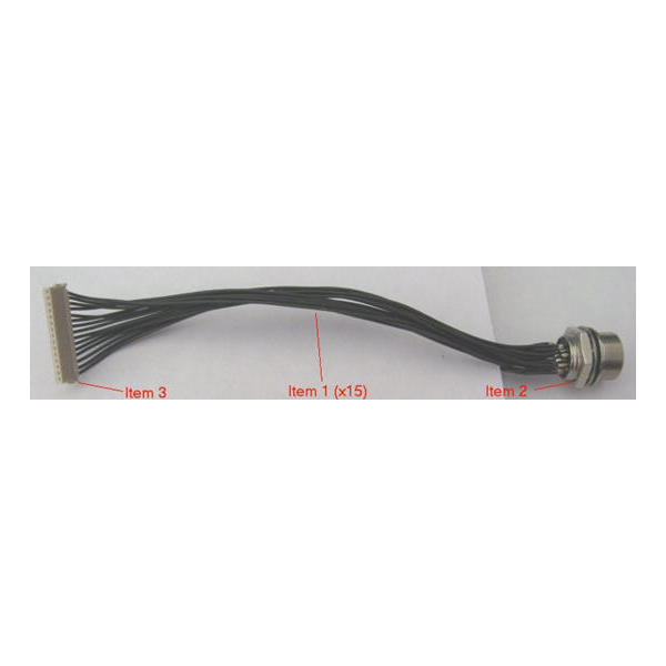
ADC Snap Cabling
wo mating cables are supplied with the camera. The first is provided for testing and setup purposes. It uses common power, video and serial plugs for easy connection to the ADC Snap Test and Control Box Assembly described below.
Item 3 in the upper photo at left is the mating connector for the ADC Snap. The wires (Item 1) are about 3 inches in length, and carry the connections to the round Hirose Bulkhead connector, Item 2. The pins on the ADC Snap connector map to the Hirose connector as shown in the lower diagram at left.
The second supplied cable is an un-terminated System Integration Cable. This has the same pin-outs as the first cable but it is left un-terminated so the user can connect the camera to other equipment in a manned or unmanned aircraft (e.g., autopilot, GPS system or video transmitter).
Note:
The external trigger/switch box that comes with the ADC Micro (and the ADC Snap) has the 15 pin Hirose flat connector and a 12" unbundled wire harness to connect the box to the camera. The utility cable is the un-terminated 6" length wires to 15 pin flat connector used for interfacing external power and control signals to the ADC Micro or Snap camera when the switch box is not connected.
The Mini MCA and ADC Air use the circular Hirose female connector on the camera and a bundled/shielded 6' cable with male Hirose connectors on each end to connect the switch box to the cameras.
The 15 pin to Hirose circular connector to 15 pin Hirose flat connector is an option for the Micro so that Micro users can utilize the Mini/Air cables or trigger/switch control box.
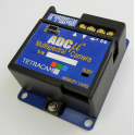
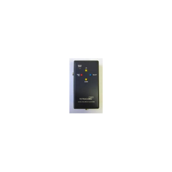
Test and Control Box Assembly
The ADC Snap Test and Control Box Assembly (shown at right) is included with each ADC Snap system. This contains buttons that enable the user to manually scroll up and down through system menus, pick a selection or take a picture. Via its 15-Pin Multi-I/O connector, this box also may be used to interconnect the camera with the RS232 transmit and receive lines of an optional GPS receiver in order to determine GPS coordinates at image capture time. The box may also be used to interconnect the camera's NTSC or PAL video signal output to an external monitor.
Camera Triggering Options
The ADC Snap may be triggered by various means depending upon the user's preference. These include:
On-Camera Shutter Release: The ADC Snap possesses a Take Pic button on the camera itself which when pressed triggers the camera
Auto-Timer: The ADC Snap may be configured to capture images continuously at intervals specified by the user via the camera's system menus. Press the Shutter Release or trigger the system via one of the methods below to begin continuously capturing images. Press the Shutter Release or trigger the camera again to stop continuous capture of images. Always stop continuously capturing images by pressing the On-Camera Shutter Release or via a trigger command prior to powering the system off. Interruption of power during continuous capture of images may damage the ADC Snap.
Remote Shutter Release: The ADC Snap's included Controller Box enables users to manually trigger the camera by pushing a button at the desired moment.
External Triggering on UAV: Used on a UAV, UAV circuitry may be patched through its un-terminated System Integration Cable (included with the system) to deliver a low-true TAKE PIC command to the ADC Snap via Pin 5.
RS-232 Triggering: The camera may be commanded to trigger by receiving an <ESC> T command via the RS232 connection on the ADC/MCA Box. Due to the delays incumbent in a serial interface, the RS232 link is more commonly used to transfer GPS position coordinates to the camera at camera trigger time. When the camera is connected to a GPS receiver via its System Integration Cable, the camera records the coordinates of the location at which each image is captured into its log file upon receiving any camera trigger command.
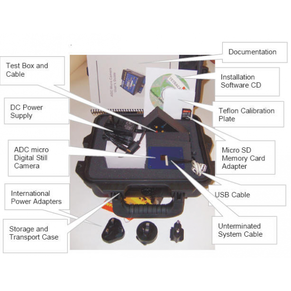
Standard System Contents
System Contents Includes:
ADC Snap Agricultural Digital Camera
CDROM with Installation Software and Documentation
Product Manual and Accessory Documentation
USB Interconnection Cable
Micro SD memory card
Micro SD to USB Reader/Adapter
DC Power Supply with International Adapters
White Teflon Calibration Plate (AKA Calibration tag or Software Calibration Tile)
Test and control box assembly and Cable
Un-terminated System Integration Cable
Hardened Plastic Storage and Transport Case
Typical Availability:
2 to 3 weeks (although faster turnaround times are
often possible). Please contact us for more information regarding configuration options, pricing and availability.
Options Commonly Purchased with this Product:
FirePoint GPS Navigation System
Tetracam Camera Calibration Service ($250.00 USD)
ADC Snap Users Manual (pdf format)
ADC Snap CAD Drawings (pdf format)
ADC Snap CAD Drawings (IGES format)
ADC Snap CAD Drawings (Solidworks format)
ADC Snap Latest Firmware Download